 中文简体
中文简体

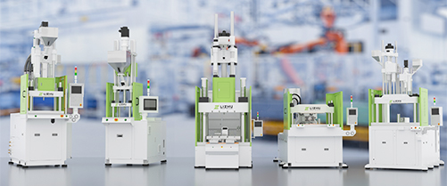

A hydraulic injection molding machine remains the most widely installed injection molding platform globally because it delivers unmatched clamping force, superior tolerance for abrasive and high-viscosity resins, and lower upfront capital cost than all-electric alternatives — making it the default choice for heavy-part, thick-wall, and large-volume plastic production across the automotive, packaging, and construction sectors.
Despite the growing visibility of all-electric injection molding machines, the hydraulic platform continues to account for the majority of global installed capacity. According to a 2024 market analysis by Mordor Intelligence, the global injection molding machine market was valued at USD 12.7 billion in 2023, with hydraulic and hybrid hydraulic systems representing approximately 58% of all units in active industrial use. In developing markets, that share climbs above 70%.
This article explains exactly how a hydraulic injection molding machine works, which applications it is best suited for, how it compares to electric and hybrid alternatives, and what specifications matter most when selecting one for your production line.
How Does a Hydraulic Injection Molding Machine Work?
A hydraulic injection molding machine uses pressurized hydraulic oil — driven by an electric motor and hydraulic pump — to power all core machine functions: clamping, injection, holding, cooling, and ejection. The hydraulic system acts as a centralized power transmission medium, converting rotary motor energy into precisely controlled linear and rotary force at each actuator.
The operating cycle of a hydraulic injection molding machine follows five sequential phases:
- Mold Closing and Clamping: The hydraulic clamping cylinder closes the two mold halves and builds clamp tonnage (typically 50–5,000 tons) to resist injection pressure. Hydraulic toggle mechanisms multiply the cylinder force by 20–40x, enabling high clamp forces from relatively compact cylinders.
- Plasticization (Screw Recovery): The rotating screw conveys, compresses, and melts plastic granules. A hydraulic motor drives the screw rotation; a back-pressure valve controls melt density.
- Injection: The hydraulic injection cylinder pushes the screw forward, injecting molten plastic into the mold cavity at pressures of 800–2,500 bar. Flow rate is controlled by a proportional hydraulic valve.
- Holding (Pack and Hold): After cavity fill, a lower holding pressure (typically 30–60% of injection pressure) is maintained to compensate for volumetric shrinkage as the part cools.
- Cooling, Mold Open, and Ejection: The part cools to a stable temperature; hydraulic actuators open the mold and activate ejector pins to release the finished part.
Core Hydraulic System Components
- Hydraulic Pump: Fixed-displacement vane pumps are standard on entry-level machines; variable-displacement piston pumps (load-sensing type) are used on premium models to reduce energy consumption during idle phases by up to 30%.
- Proportional Valve System: Electrohydraulic proportional valves enable closed-loop pressure and flow control, giving modern hydraulic machines repeatability comparable to servo-electric systems on many metrics.
- Oil Cooling Circuit: Hydraulic oil must be maintained at 35–55°C for stable viscosity. Water-cooled oil-to-water heat exchangers are standard; air-blast coolers are used in water-scarce installations.
- Accumulator (on high-speed machines): A nitrogen-charged hydraulic accumulator stores pressurized oil for high-speed injection events, enabling injection fill times below 0.3 seconds for thin-wall applications.
- Servo Hydraulic Upgrade (optional): Replacing the fixed-speed motor with a servo motor driving the hydraulic pump creates a "servo-hydraulic" system — retaining full hydraulic force capability while cutting energy use by 40–70%.
Which Applications Are Best Suited for a Hydraulic Injection Molding Machine?
Hydraulic injection molding machines are the dominant choice for large-part production, high-tonnage clamping, and processing of abrasive or filled resins — applications where the raw force density and durability of hydraulics outweigh the energy efficiency advantage of all-electric machines.
| Industry | Typical Parts | Clamp Force Required | Why Hydraulic Wins |
| Automotive | Bumpers, dashboards, door panels | 800–3,500 tons | Large projected area; glass-filled resins |
| Packaging | Crates, pallets, buckets, caps | 200–2,000 tons | High-cycle durability; low part cost |
| Construction | Pipe fittings, junction boxes, formwork | 500–5,000 tons | Thick wall; mineral-filled PP/PA |
| Agriculture | Irrigation parts, fertilizer trays | 300–1,200 tons | Recycled/contaminated resin tolerance |
| Consumer Goods | Chairs, storage containers, toys | 200–800 tons | Low capital cost; flexible tooling |
| Electrical / Industrial | Enclosures, cable housings, panels | 150–600 tons | Multi-material; insert molding capability |
Table 1: Key industries, typical applications, and reasons for choosing hydraulic injection molding machines over electric alternatives.
How Does a Hydraulic Injection Molding Machine Compare to Electric and Hybrid Models?
In a direct head-to-head comparison, hydraulic injection molding machines lead on clamping force ceiling, purchase price, and material versatility, while all-electric machines outperform them on energy efficiency and precision for small, tight-tolerance parts. Hybrid servo-hydraulic systems occupy a compelling middle ground.
| Parameter | Hydraulic | All-Electric | Servo-Hydraulic (Hybrid) |
| Max Clamp Force | Up to 10,000+ tons | Up to 650 tons (typical) | Up to 4,000 tons |
| Energy Consumption | Baseline (100%) | 30–50% of hydraulic | 40–65% of hydraulic |
| Purchase Price (500t) | USD 80,000–150,000 | USD 180,000–320,000 | USD 120,000–220,000 |
| Repeatability (shot weight CV%) | 0.5–1.5% | 0.1–0.3% | 0.2–0.6% |
| Abrasive Resin Tolerance | Excellent | Limited (ballscrew wear) | Good |
| Hydraulic Oil Required | Yes (300–1,000 L) | No | Yes (reduced volume) |
| Cleanroom Suitability | Limited (oil mist risk) | ISO Class 7–8 capable | With mitigation measures |
| Maintenance Cost (annual) | Medium (oil, seals, filters) | Low (no hydraulic system) | Low-Medium |
| Noise Level (dB) | 72–85 dB | 58–68 dB | 62–72 dB |
Table 2: Comparative performance parameters for hydraulic, all-electric, and servo-hydraulic injection molding machines. Data compiled from EUROMAP technical standards and industry equipment specifications (2024).
The data reveals a clear strategic picture: for parts requiring more than 650 tons of clamp force, hydraulic remains the only practical platform. For precision micro-parts or cleanroom medical applications below 200 tons, all-electric is superior. For everything in between — which is most industrial production — the servo-hydraulic hybrid offers the best total cost of ownership over a 10-year production horizon.
What Specifications Matter Most When Buying a Hydraulic Injection Molding Machine?
The six most critical specifications for a hydraulic injection molding machine are clamping force, injection unit size, tie-bar spacing, injection pressure, dry cycle time, and hydraulic system type — each directly determining which parts can be run and at what economic efficiency.
1. Clamping Force (Tonnage)
Clamping force is the machine's primary classification parameter, expressed in metric tons (t) or kilonewtons (kN). The required clamp force is calculated as: Clamp Force (t) = Projected Part Area (cm²) × Cavity Pressure (t/cm²). For standard PP and PE resins, cavity pressure is typically 0.3–0.5 t/cm²; for PC, PA66-GF30, and ABS, it rises to 0.5–0.8 t/cm². Always add a 15–20% safety margin above the calculated minimum to ensure complete cavity fill and dimensional stability.
2. Injection Unit Size (Shot Volume and Screw Diameter)
The injection unit must be sized so that each production shot consumes 20–80% of the screw's theoretical shot volume. Operating below 20% causes excessive resin residence time and thermal degradation; above 80%, pressure losses rise and fill control deteriorates. Screw L/D ratios of 20:1 to 24:1 are standard for general-purpose resins; heat-sensitive materials (PVC, POM) require 18:1 or shorter.
3. Tie-Bar Spacing (Platen Gap)
Tie-bar spacing determines the maximum mold width that can be installed. Mold width should be at least 30–50 mm smaller than tie-bar spacing on each side to allow safe mold installation. For automotive bumper molds (often 1,200–1,600 mm wide), tie-bar spacings of 1,600–2,200 mm are required, pointing directly to machines in the 1,500–3,500 ton range.
4. Maximum Injection Pressure
Standard hydraulic injection molding machines operate at injection pressures of 1,400–2,200 bar. High-performance models with accumulators can reach 2,500 bar for thin-wall or long-flow applications. Engineering resins such as liquid crystal polymer (LCP) and long-fiber-reinforced nylon may require sustained pressures above 2,000 bar — a specification that eliminates many entry-level hydraulic machines from consideration.
5. Dry Cycle Time
Dry cycle time (the time to complete one mold open-close cycle without injection) is a proxy for machine mechanical speed. For a 500-ton hydraulic machine, a competitive dry cycle time is under 4.5 seconds. A machine with a dry cycle above 6 seconds on a 500-ton frame will create cycle time bottlenecks in applications where part cooling time is under 12 seconds.
6. Hydraulic System Type: Fixed-Pump vs. Variable-Pump vs. Servo-Hydraulic
Fixed-displacement vane pump systems are the lowest-cost option but consume full motor power throughout the cycle, even during cooling when no hydraulic flow is needed. Variable-displacement piston pumps reduce energy use by 15–25% by matching pump output to demand. Servo-hydraulic systems — using a servo motor to drive the pump at variable speed — achieve 40–70% energy reduction versus fixed-pump machines, with payback periods typically below 3 years at two-shift operation (source: Plastics Technology, 2023).
What Are the Real Energy Costs of Running a Hydraulic Injection Molding Machine?
Energy is the largest variable operating cost for a hydraulic injection molding machine, typically representing 60–75% of total operating cost excluding raw material. Understanding consumption by cycle phase allows targeted optimization.
| Cycle Phase | Energy Share (Fixed Pump) | Energy Share (Servo-Hydraulic) | Optimization Potential |
| Plasticization | 30–35% | 28–32% | Low (screw work is essential) |
| Injection and Holding | 20–25% | 18–22% | Medium (accumulator helps) |
| Clamping (open/close) | 15–20% | 10–14% | High (servo speed matching) |
| Cooling (idle pump) | 20–30% | 2–5% | Very High (biggest saving) |
| Ejection | 3–6% | 2–4% | Low |
Table 3: Energy consumption breakdown by cycle phase for fixed-pump hydraulic vs. servo-hydraulic injection molding machines. Source: EUROMAP 60.1 energy measurement methodology, 2023.
The most impactful single upgrade is addressing idle-phase energy waste. On a fixed-pump machine with a 20-second cycle, the pump runs at full power for approximately 8–10 seconds of cooling during which no hydraulic work is performed. A servo-hydraulic drive reduces pump speed to near-zero during this phase, eliminating 20–30% of total machine energy draw. For a 200 kW rated machine running two shifts at USD 0.12/kWh, this translates to savings of USD 18,000–28,000 per year per machine.
How to Maintain a Hydraulic Injection Molding Machine for Maximum Uptime
Proactive maintenance of a hydraulic injection molding machine can achieve overall equipment effectiveness (OEE) above 85%, while neglected machines typically drop below 65% OEE within three years due to oil contamination, seal degradation, and valve spool wear. The single most important maintenance action is hydraulic oil quality management.
Hydraulic Oil Management
- Maintain ISO cleanliness class 16/14/11 or better (per ISO 4406). Contamination above class 18/16/13 accelerates proportional valve wear by a factor of 3–5x.
- Sample oil every 500 operating hours for particle count, viscosity, and water content analysis. Replace oil if viscosity deviates more than 10% from specification or water content exceeds 0.1%.
- Replace return-line filters every 1,000 hours or when the differential pressure indicator signals bypass — whichever comes first.
- Maintain oil temperature at 40–50°C during operation. Oil above 65°C degrades additive packages, accelerates seal wear, and reduces viscosity below the minimum required for reliable valve operation.
Preventive Maintenance Schedule
| Interval | Task | Acceptance Criterion |
| Daily | Check oil level, temperature, and alarm log; inspect for hydraulic leaks | Oil at midpoint sight glass; no active leaks |
| Weekly | Inspect cylinder rod seals; clean air vents on oil tank; check tie-bar lubrication | No weeping seals; vents unobstructed |
| Monthly | Oil sample analysis; test safety door interlocks; check heat exchanger flow | ISO 16/14/11 or cleaner; interlocks function within 0.5s |
| Quarterly | Replace return-line filters; inspect screw and barrel wear; calibrate pressure transducers | Screw flight clearance within OEM spec; pressure error below ±1% |
| Annually | Full oil change; pump efficiency test; proportional valve cleaning and calibration | Pump volumetric efficiency above 92%; valve hysteresis below 1% |
| Every 5 Years | Replace all hydraulic hoses; overhaul main pump and clamp cylinder seals | Restore to original performance specification |
Table 4: Preventive maintenance schedule for hydraulic injection molding machines operating on two-shift production schedules.
What Are the Most Common Faults in Hydraulic Injection Molding Machines and How to Fix Them?
The five most common faults in hydraulic injection molding machines account for over 80% of unplanned downtime, and all five are preventable with proper oil management, scheduled maintenance, and operator training.
- Slow or Erratic Clamp Closing (Root Cause: Oil Contamination or Proportional Valve Wear): Particles in oil score proportional valve spools, causing hysteresis and sluggish response. Resolution: sample oil, replace filters, clean or replace the affected valve spool. Average repair time: 2–4 hours.
- Inconsistent Shot Weight (Root Cause: Check Valve Wear in Screw Tip): A worn non-return valve allows melt backflow during injection, reducing shot consistency. Signs include part weight variation above 1.5% CV. Resolution: replace screw tip assembly. Cost: USD 800–3,500 depending on screw diameter.
- Oil Overheating above 65°C (Root Cause: Fouled Heat Exchanger or Oversized Back-Pressure): Scale buildup on the water side of the oil cooler reduces heat transfer efficiency by up to 60%. Resolution: acid-flush the heat exchanger; verify cooling water flow rate. Also review back-pressure settings — excessive back-pressure generates significant frictional heat in the screw.
- Hydraulic Cylinder Seal Leaks (Root Cause: High-Cycle Fatigue or Contaminated Oil): Rod seals on clamp cylinders have a typical service life of 8,000–15,000 operating hours under clean-oil conditions. Contaminated oil cuts this to 2,000–4,000 hours. Seal replacement is a planned 4–8 hour maintenance job per cylinder.
- Pump Cavitation Noise (Root Cause: Low Oil Level, Air Ingestion, or Cold Startup): Cavitation produces a distinctive high-frequency rattling from the pump and causes rapid pump wear. Resolution: check oil level, inspect suction line for air entry points, and implement a 3–5 minute warm-up idle routine at startup in ambient temperatures below 15°C.
Frequently Asked Questions About Hydraulic Injection Molding Machines
Q: How long does a hydraulic injection molding machine last?
A well-maintained hydraulic injection molding machine from a reputable manufacturer typically remains in productive service for 15–25 years. The hydraulic system (pump, valves, cylinders) generally requires a major overhaul at 8–12 years. The machine frame, platens, and tie-bars are designed for the full equipment life. Screw and barrel sets typically need replacement every 3–7 years depending on resin abrasiveness.
Q: What type of hydraulic oil should be used?
Most hydraulic injection molding machines are designed for anti-wear hydraulic oil (HM type, ISO VG 46 or ISO VG 68). ISO VG 46 is standard for ambient temperatures of 15–35°C; ISO VG 68 is preferred for machines in environments above 35°C or machines with large oil volumes that warm slowly. Always confirm the OEM specification before switching oil grades, as mixing different additive packages can cause foam formation and sludge.
Q: Can a hydraulic injection molding machine process recycled plastics?
Yes, and this is one of the key advantages of hydraulic machines over all-electric models. The robust hydraulic drive tolerates the higher process variability inherent in recycled resins — including viscosity fluctuations, contamination, and inconsistent melt flow index — without the precision mechanical components (ballscrews, servo axes) that can be damaged by abrasive recycled content. With a hardened barrel and screw, a hydraulic injection molding machine can process post-consumer recycled PP and HDPE at industrial scale.
Q: Is it worth retrofitting an old hydraulic machine with a servo drive?
For machines in good mechanical condition with less than 12 years of service, a servo-hydraulic retrofit typically delivers a payback period of 18–36 months at two-shift production rates. The retrofit replaces the fixed-speed motor and fixed-displacement pump with a servo motor and variable-displacement pump. Installation typically takes 2–3 days. The typical energy saving of 40–60% justifies the investment whenever remaining useful machine life exceeds 5 years.
Q: What is the difference between toggle clamp and direct hydraulic clamp designs?
Toggle clamp designs use a mechanical linkage to amplify cylinder force, achieving high clamp tonnage with a smaller cylinder and faster dry cycle times. They are standard on machines up to approximately 2,000 tons. Direct hydraulic clamp (also called full hydraulic clamp) applies force directly from one or more large hydraulic cylinders — offering more consistent clamp force distribution across the mold face and simpler adjustment for different mold heights. Direct hydraulic designs are preferred for molds requiring highly uniform clamping, such as large multi-cavity optical or surface-finish-critical parts.
Q: What safety standards apply to hydraulic injection molding machines?
In Europe, hydraulic injection molding machines must comply with EN ISO 20430:2021 (Safety Requirements for Plastics and Rubber Machinery — Injection Moulding Machines), which covers safety guards, emergency stops, hydraulic pressure relief, and CE marking. In North America, ANSI/SPI B151.1 applies. In China, GB 22530 is the applicable national standard. All modern machines should include safety category 3 or 4 emergency stop circuits per ISO 13849-1 and hydraulic pressure relief valves set no more than 10% above system working pressure.
Conclusion: The Strategic Case for the Hydraulic Injection Molding Machine in Modern Manufacturing
The narrative that hydraulic technology is obsolete in injection molding is not supported by industrial reality. The hydraulic injection molding machine remains the only platform capable of delivering more than 1,000 tons of clamping force at commercially viable capital cost — a capability that cannot be replicated by electric alternatives at any price point today. For the automotive, construction, and heavy packaging sectors, this is not a legacy choice; it is an engineering necessity.
At the same time, the evolution of servo-hydraulic drives, variable-displacement pumps, closed-loop proportional control, and smart oil monitoring has transformed the hydraulic injection molding machine from an energy-intensive workhorse into a precision, energy-aware production platform. The performance gap between hydraulic and electric machines on energy and repeatability metrics is narrowing with each generation.
The right decision framework is not hydraulic versus electric — it is matching the right technology to the specific requirements of your parts, materials, production volume, and 10-year cost horizon. For high-tonnage, abrasive-resin, or large-part applications, a modern servo-hydraulic injection molding machine represents the best combination of force capability, total cost of ownership, and operational robustness available today.


