 中文简体
中文简体
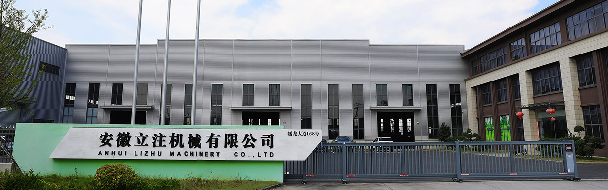
LIZHU Machinery Co., Ltd. was founded in 2011, is a leading company in high-speed precision injection molding...
View More
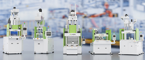
At present, we have various models of standard machines, skateboard machines, disc machines, and multi-color machines under 2000 tons.
View More
Check out the latest from the injection molding machine about the topics relevant to your industry and manufacturing process.
View More

Industry News
Home / News / Industry News / Injection Molding Machine Cutaway: Vertical vs Horizontal Structure Guide
 Home / News / Industry News / Injection Molding Machine Cutaway: Vertical vs Horizontal Structure Guide
 Injection Molding Machine Cutaway: Vertical vs Horizontal Structure Guide
2026-08-07
Slice an injection molding machine down the middle, and the cutaway view shows exactly how polymer pellets become finished parts: where the screw melts and injects material, how the mold is held shut under tonnage, and how the part is ejected after cooling. For engineers, purchasing teams, and maintenance staff, that internal picture is a practical decision tool. It explains why some machine configurations suit insert molding, which structural details affect maintenance, and what to check when comparing quotations. This guide covers the four core subsystems in any injection molding machine cutaway, compares vertical and horizontal layouts, and connects structure to real selection decisions.
The Four Core Subsystems in an Injection Molding Machine Cutaway
Every injection molding machine, regardless of manufacturer or configuration, can be reduced to four functional systems: the injection unit, the clamping unit, the drive unit, and the control system. A cutaway drawing shows how these systems are arranged, and that arrangement determines what the machine does best. The same injection unit can deliver a precise shot of nylon into a mold whether it is mounted horizontally or vertically; the real difference lies in how the clamping unit and the mold are aligned around it.
Injection Unit: From Pellets to Melt
Find the injection unit in a cutaway and you will see a long cylinder with a hopper on top. Pellets fall from the hopper into a heated barrel, where a reciprocating screw rotates to convey, compress, and melt them. Once enough melt accumulates ahead of the screw, the screw stops turning and advances like a plunger, forcing the melt through the nozzle into the closed mold. The screw-as-plunger analogy appears in many technical guides because it matches what the drawing shows: one continuous stroke delivering the full shot.
The key specification is shot size, the maximum volume of melt injected in one cycle, usually rated in ounces of general-purpose polystyrene or cubic centimeters. A common selection rule is to specify a machine whose shot size is 30 to 40 percent above the combined weight of part and runner. That margin absorbs viscosity variation without running the screw at its forward limit on every shot.
Clamping Unit: Holding the Mold Under Pressure
The clamping unit is the heavy structure that opens and closes the mold. It uses a stationary platen, a moving platen, and tie bars that guide the moving platen in a straight line. During injection, polymer enters the cavity at high pressure and pushes against both mold halves. If clamping force, expressed in tons, is too low, the mold opens slightly and melt escapes along the parting line, causing flash. Flash adds a trimming step and creates scrap, so clamp force must always exceed the separating force of the shot.
Clamping systems come in two structural families. Toggle machines multiply force through mechanical links for fast, energy-efficient cycling. Direct hydraulic machines push the platen with a large cylinder for finer pressure control across the stroke. The cutaway shows which family a machine belongs to, and the choice affects cycle time, energy cost, and maintenance.
Ejection and Control Systems: Completing the Cycle
After cooling, the mold opens and ejector pins, mounted on an ejector plate behind the moving platen, push the part off the mold face. Two details matter: ejector stroke must exceed part depth for clean release, and pin layout must match part geometry to avoid visible marks.
The control system coordinates everything else: barrel zone temperatures, injection pressure and speed, clamping force, and cycle timing are managed in a closed loop. On modern machines, the controller also logs production data and communicates with automation, which is why drive and control choices are now part of the selection conversation.
Vertical vs. Horizontal: How the Cutaway Changes
Most cutaway diagrams online show a horizontal machine: barrel pointing sideways, mold platens upright, parts ejected to a conveyor. A vertical machine rearranges the same subsystems along a vertical axis. The clamping unit stacks upward, the mold parting line lies horizontal, and the injection unit sits above the mold, injecting downward. That is not cosmetic; it changes the machine's operating character from the ground up.
| Feature | Horizontal machine | Vertical machine |
|---|---|---|
| Injection unit orientation | Horizontal, pointing sideways | Vertical, pointing downward |
| Mold parting line | Vertical plane | Horizontal plane |
| Insert placement | Against a vertical face; can shift | Resting on a horizontal face; stable |
| Floor footprint | Long, linear layout | Compact, upright layout |
| Part ejection | To the side via conveyor | Downward into a container |
| Typical applications | General-purpose molding, high cavitation | Insert molding, overmolding, encapsulation |
Three practical consequences follow directly. First, the horizontal mold face creates a stable work surface for inserts. A metal nut, pin, or terminal stays where the operator put it while the machine closes; on a horizontal machine, the same insert rests against a vertical face and can shift. Second, a vertical machine occupies much less floor space, often about one third of an equivalent horizontal model, which suits compact cells near assembly lines. Third, ejection works with gravity: parts fall directly into a bin or conveyor below the mold, reducing the need for extraction robots.
Where Vertical Machines Excel: Insert Molding and Overmolding
Insert molding is the textbook application for vertical machine geometry. Place a metal insert in the lower mold half, the machine closes, plastic is injected around the insert, and the assembly is ejected. Because the parting line is horizontal, gravity holds the insert in place just before clamping, and the operator or robot loads from above without reaching around a vertical platen.
Overmolding follows the same logic. A substrate, whether metal, hard plastic, or a cable assembly, sits in the mold, and a second polymer is molded over it. When this architecture is combined with a sliding table, the lower mold half moves out for loading while the cycle continues above, so loading runs in parallel with injection and cooling. That is the structural basis of efficient insert molding lines, and it is why a standard vertical injection molding machine is often the first configuration molders evaluate when starting insert molding.
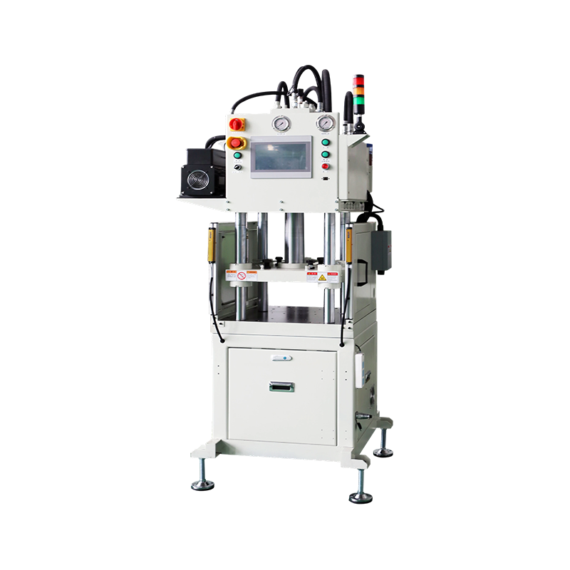
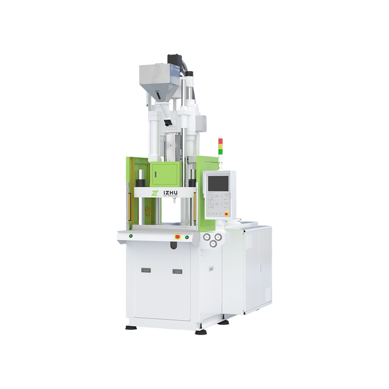 Standard vertical injection molding machine Supplier, CompanyLIZHU Machinery is China wholesale Standard vertical injection molding machine manufacturers supplier and company, offering wholesale sol...View Product →
Key Structural Features to Inspect in a Vertical Machine Cutaway
Four structural details deserve close attention in a vertical machine's cutaway:
- Clamping cylinder placement. Most vertical machines place the clamp cylinder below the lower platen and push upward. Check how the moving platen is guided; long guide posts and adequate bearing surfaces keep the mold halves aligned.
- Sliding or rotary table construction. In sliding-table machines, the lower mold half extends out for loading. Inspect the support rails, locating pins, and table support at full extension; a table that loses support at the front of the stroke will cause mold deflection. This is why a single sliding-platen vertical injection molding machine
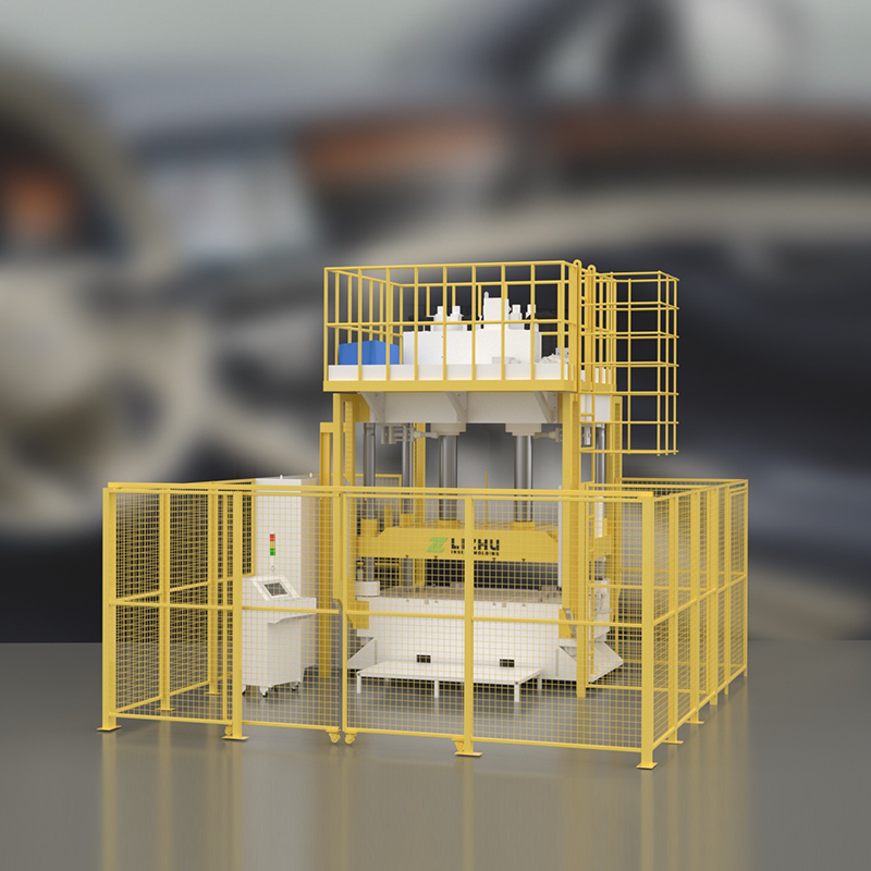
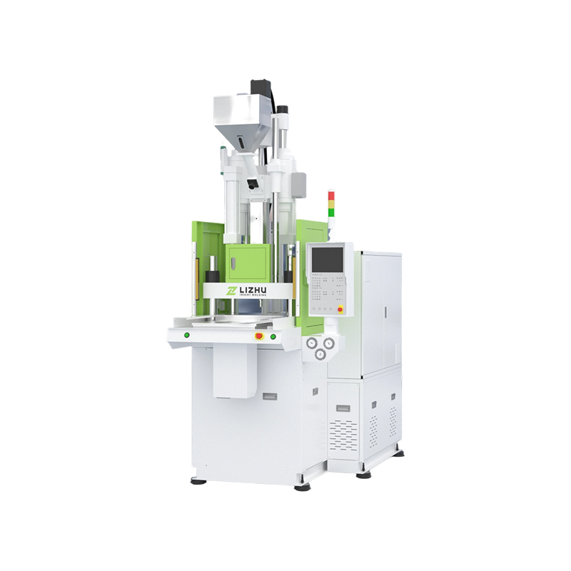 Single Sliding Vertical Injection Molding Machine ManufacturersLIZHU Machinery is China single sliding vertical injection molding machine manufacturers and custom factory, offering wholesale solutions...View Product → warrants careful structural review before purchase.
 - Ejection configuration. Confirm whether ejection acts from the top, bottom, or both. Stroke, force, and pin pattern must fit your parts, not just the mold maker's standard.
- Drive system. Hydraulic power packs are still common, but servo-driven pumps and all-electric drives are gaining ground because they cut idle energy use and improve repeatability. The technical case is explained in our review of why servo drives are transforming vertical injection molding machines.
Maintenance Insights from the Cutaway
A cutaway is also a maintenance map. It shows where wear begins and which components deserve scheduled inspection.
- Screw and barrel. Glass-filled resins wear the screw flight and barrel bore. Periodic checks of screw diameter and surface condition protect shot weight consistency.
- Heater bands. Temperature uniformity along the barrel controls melt viscosity; damaged bands produce parts with inconsistent gloss or dimensions.
- Hydraulic oil cleanliness. Hydraulic machines most often fail because of contaminated oil. Check the return filter and oil condition on a fixed schedule.
- Tie bars and toggle joints. Uneven lubrication leads to unbalanced clamping force. Grease the tie bars, toggle pins, and ejector bushings regularly.
- Sliding and rotary tables. Guide rails, locating pins, and indexing mechanisms wear with every cycle and directly affect mold alignment.
A structured walkthrough of these routines is available in our guide to key maintenance points for injection molding machine mechanical parts, which lists inspection intervals and warning signs in shift-based order.
How to Read a Cutaway When Evaluating a Machine
Use this sequence when a supplier presents a cutaway during quotation review:
- Injection unit first. Check screw diameter, effective stroke, and L/D ratio. A general-purpose screw around 20:1 is typical; engineering resins may need different geometry. Compare rated shot size with your part and runner weight, keeping the 30 to 40 percent margin.
- Clamping unit second. Identify toggle or hydraulic structure, then record tie-bar spacing and maximum daylight between platens. These dimensions define the largest mold the machine accepts; tonnage alone does not.
- Ejection system third. Match ejector stroke to the depth of your deepest part and confirm that the ejection pattern can be customized.
- Drive and control fourth. Establish whether the machine is hydraulic, servo-hydraulic, or electric, and review the controller's data logging and automation capabilities.
| Step | What to check | Why it matters |
|---|---|---|
| 1. Injection unit | Screw L/D, shot size, nozzle type | Determines melt quality and shot weight margin |
| 2. Clamping unit | Toggle vs. hydraulic, tie-bar spacing | Defines mold size limit and closing-speed behavior |
| 3. Ejection system | Ejector stroke, pin layout | Ensures clean part release and acceptable cosmetic quality |
| 4. Drive and control | Hydraulic vs. servo vs. electric, controller features | Affects energy cost, repeatability, and automation fit |
Conclusion: From Cutaway to Confident Selection
An injection molding machine cutaway is a decision tool, not just a technical illustration. It lets you translate "should we use a vertical machine for insert molding?" into a geometric answer. The vertical layout places the injection unit above the mold, turns the parting line horizontal, and lets gravity hold inserts and release parts. That is why vertical machines dominate insert molding, overmolding, and mold-in-component processes.
Once you know what to examine, injection unit, clamping unit, ejection system, and drive type, you can review a supplier's cutaway with confidence and ask precise questions about screw geometry, sliding-table support, ejection configuration, and drivetrain efficiency. If the structural answers match your production needs, compare actual machine specifications against your mold size and automation goals before ordering.
News categories
Product categories
Exhibition Information
-
How to choose high cost-effective standard vertical injection molding machines?
Oct 10,2025 -
Key points for maintenance and upkeep of the mechanical part of the vertical injection molding machine
Oct 10,2025 -
Why do the medical and 3C industries favor vertical electric injection molding machines?
Oct 10,2025


-
 +86-(0)512-6598 3406
 -
 +86-138 6210 7502
 -

-
 Zhaoyao Science and Technology Park, No. 573 Ruyuan Road, Chengyang Subdistrict, Xiangcheng District, Suzhou, Jiangsu Province, China
Copyright © 2025 Suzhou Lizhu Machinery Co., Ltd. All Rights Reserved.
China precision injection molding machine manufacturers custom precision injection molding machine supplier
